How to Create 2d Drawing in Autocad
- Introduction
- Discovering FreeCAD
- What is FreeCAD?
- Installing
- Installing on Windows
- Installing on Linux
- Installing on Mac OS
- Uninstalling
- Setting basic preferences
- Installing additional content
- The FreeCAD interface
- Workbenches
- The interface
- Customizing the interface
- Navigating in the 3D view
- A word about the 3D space
- The FreeCAD 3D view
- Selecting objects
- The FreeCAD document
- Parametric objects
- Import and export to other filetypes
- Working with FreeCAD
- All workbenches at a glance
- Traditional modeling, the CSG way
- Traditional 2D drafting
- Modeling for product design
- Preparing models for 3D printing
- Exporting to slicers
- Converting objects to meshes
- Using Slic3r
- Using the Cura addon
- Generating G-code
- Generating 2D drawings
- BIM modeling
- Using spreadsheets
- Reading properties
- Writing properties
- Creating FEM analyses
- Creating renderings
- Python scripting
- A gentle introduction
- Writing Python code
- Manipulating FreeCAD objects
- Vectors and Placements
- Creating and manipulating geometry
- Creating parametric objects
- Creating interface tools
- A gentle introduction
- The community
You might be interested by FreeCAD because you already have some technical drawing experience, for example with software like AutoCAD. Or you already know something about design, or you prefer to draw things before building them. In any case, FreeCAD features a more traditional workbench, with tools found in most 2D CAD applications: The Draft Workbench.
The Draft Workbench, although it adopts ways of working inherited from the traditional 2D CAD world, is not limited at all to the 2D realm. All its tools work in the whole 3D space and many of the Draft tools, for example ![]() Move or
Move or ![]() Rotate, are commonly used all over FreeCAD because they are often more intuitive than changing placement parameters manually.
Rotate, are commonly used all over FreeCAD because they are often more intuitive than changing placement parameters manually.
Among the tools offered by the Draft Workbench, you will find traditional drawing tools like ![]() Line,
Line, ![]() Circle, or
Circle, or ![]() Wire (polyline), modification tools like
Wire (polyline), modification tools like ![]() Move,
Move, ![]() Rotate or
Rotate or ![]() Offset, a working plane/grid system that allows you to define precisely in which plane you are working, and a complete snapping system that makes it very easy to draw and position elements precisely in relation to each other.
Offset, a working plane/grid system that allows you to define precisely in which plane you are working, and a complete snapping system that makes it very easy to draw and position elements precisely in relation to each other.
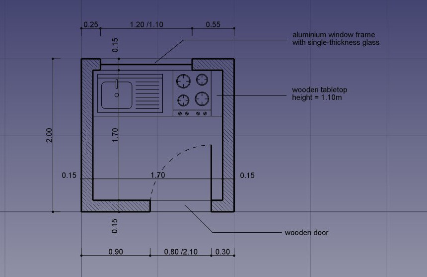
To showcase the workflow and possibilities of the Draft Workbench, we will walk through a simple exercise, the result of which will be this little drawing, showing the floor plan of a small house that contains only a kitchen top (A pretty absurd floor plan, but we can do what we want here, can't we?):
- Switch to the Draft Workbench
- As in all technical drawing applications, it is wise to set up your environment correctly, it will save you a lot of time. Configure the grid and working plane, Text and Dimension settings to your liking in menu Edit → Preferences → Draft. In this exercise, however, we will act as if these settings were left at their default values.

- One option might need your attention, though: the "Fill objects with faces whenever possible" option. If this is marked, closed objects like rectangles or circles will be filled with a face by default, which can make snapping to underlying objects difficult. You can either turn this option off now, or, later on, turn the "Make Face" property of each individual object off, to prevent them from creating a face.
- The Draft Workbench also has two special toolbars: One with visual settings, where you can change the current working plane, turn construction mode on/off, set the line color, face color, line weight and text size to be used for new objects, and another one with snap locations. There, you can turn the grid on/off and set/unset individual Snap locations:
![]()
- Turning on all the snap buttons is convenient, but also makes drawing slower, as more calculation needs to be done when you move the mouse cursor. It is often better to keep only the ones you will actually use.
- Let's start by turning construction mode on, which will allow us to draw some guidelines on which we will draw our final geometry.
- If you wish, set the working plane to XY. If you do this, the working plane won't change, no matter the current view. If not, the working plane will adapt automatically to the current view, and you should take care of staying in top view whenever you want to draw on the XY (ground) plane.
- Then, select the
 Rectangle tool and draw a rectangle, starting at point (0,0,0), of 2 meters by 2 meters (leave the Z at zero). Note that most of the Draft commands can be fully performed from the keyboard, without touching the mouse, using their two-letter shortcut. Our first 2x2m rectangle can be done like this: re 0 Enter 0 Enter 0 Enter 2m Enter 2m Enter 0 Enter.
 - Duplicate that rectangle by 15cm inside, using the
 Offset tool, turning its Copy mode on, and giving it a distance of 15cm:

- We can then draw a couple of vertical lines to define where our doors and windows will be placed, using the
 Line tool (note that the "relative" mode box should be unchecked for this step). The crossing of these lines with our two rectangles will give us useful intersections to snap our walls to. Draw the first line from point (15cm, 1m, 0) to point (15cm, 3m, 0).
 - Duplicate that line 5 times, using the
 Move tool with Copy mode turned on. Turn also the Relative mode on, which will allow us to define movements in relative distances, which is easier than calculating the exact position of each line. Perform each move operation in sequence on the line that was created immediately prior. Give each new copy any start point, you can leave it at (0,0,0) for example, and the following relative endpoints:
 - line001: x: 10cm
- line002: x: 120cm
- line003: x: -55cm, y: -2m
- line004: x: 80cm
- line005: x: 15cm


- We can change their default grey color to a nice hatch pattern, by selecting both walls, then setting their Pattern property to Simple, and their Pattern size to your liking, for example 0.005.

- We can now hide the construction geometry by right-clicking the Construction group and choose Hide Selection.
- Let's now draw the windows and doors. Make sure the
 midpoint snap is turned on, and draw six lines as follow:


- We can now start placing some furniture. To begin with, let's place a counter by drawing a rectangle from the upper left inner corner, and giving it a width of 170cm and a height of -60cm. In the image below, the Transparency property of the rectangle is set to 80%, to give it a nice furniture look.
- Then let's add a sink and a cookertop. Drawing these kinds of symbols by hand can be very tedious, and they are usually easy to find on the internet, for example on http://www.cad-blocks.net . In the Downloads section below, for convenience, we separated a sink and a cookertop from this project, and saved them as DXF files.You can download these two files by visiting the links below, and right-clicking the Raw button, then choosing save as.
- Inserting a DXF file into an opened FreeCAD document can be done either by choosing the File → Import menu option, or by dragging and dropping the DXF file from your file explorer into the FreeCAD window. The contents of the DXF files might not appear right on the center of your current view, depending on where they were in the DXF file. You can use menu View → Standard views → Fit all to zoom out and find the imported objects. Insert the two DXF files, and move them to a suitable location on the tabletop:

- We can now place a couple of dimensions using the
 Dimension tool. Dimensions are drawn by clicking 3 points: the start point, an end point, and a third point to place the dimension line. To make horizontal or vertical dimensions, even if the two first points are not aligned, press Shift while clicking the second point.
 - You can change the position of a dimension text by double-clicking the dimension in the tree view. A control point will allow you to move the text graphically. In our exercise, the "0.15" texts have been moved away for better clarity.
- You can change the contents of the dimension text by editing their Override property. In our example, the texts of the door and window dimensions have been edited to indicate their heights:

- Let's add some description texts using the
 Text tool. Click a point to position the text, then enter the lines of text, pressing Enter after each line. To finish, press Enter twice.
 - The indication lines (also called "leaders") that link the texts to the item they are describing are simply done with the Wire tool. Draw wires, starting from the text position, to the place being described. Once that is done, you can add a bullet or arrow at the end of the wires by setting their End Arrow property to
true

- Our drawing is now complete! Since there are quite a number of objects there, it would be wise do some cleaning and restructure everything into nice groups, to make the file easier to understand for other people:

- We can now print our work by placing it on a Drawing sheet, which we will show later in this manual, or directly export our drawing to other CAD applications, by exporting it to a DXF file. Simply select our "Floor plan" group, select menu File → Export, and select the Autodesk DXF format. The file can then be opened in any other 2D CAD application such as LibreCAD. You might notice some differences, depending on the configurations of each application.

- The most important thing about the Draft Workbench, however, is that the geometry you create with it can be used as a base or easily extruded into 3D objects, simply by using the
 Part_Extrude tool from the Part Workbench, or, to stay in Draft, the
  Trimex (Trim/Extend/Extrude) tool, which under the hood performs a Part Extrusion, but does it "the Draft way", that is, allows you to indicate and snap the extrusion length graphically. Experiment extruding our walls as shown below.
 - By pressing the
 working plane button after selecting a face of an object, you are also able to place the working plane anywhere, and therefore draw Draft objects in different planes, for example on top of the walls. These can then be extruded to form other 3D solids. Experiment setting the working plane on one of the top faces of the walls, then draw some rectangles up there.

- All kinds of openings can also be done as easily by drawing Draft objects on the faces of walls, then extruding them, then using the boolean tools from the Part Workbench to subtract them from another solid, as we saw in the previous chapter.
Fundamentally, what the Draft Workbench does is to provide graphical ways to create basic Part operations. While in Part you will usually position objects by setting their placement parameter, in Draft you can do it on-screen. There are times when one is better, other times when the other is preferable. Don't forget, you can create custom toolbars in one of these workbenches, add the tools from the other, and get the best of both worlds.
Downloads
- The file created during this exercise: https://github.com/yorikvanhavre/FreeCAD-manual/blob/master/files/cabin.FCStd
- The sink DXF file: https://github.com/yorikvanhavre/FreeCAD-manual/blob/master/files/sink.dxf
- The cookertop DXF file: https://github.com/yorikvanhavre/FreeCAD-manual/blob/master/files/cooktop.dxf
- The final DXF file produced during this exercise: https://github.com/yorikvanhavre/FreeCAD-manual/blob/master/files/cabin.dxf
- The Draft Workbench
- Snapping
- The Draft working plane
Source: https://wiki.freecadweb.org/Manual:Traditional_2D_drafting
0 Response to "How to Create 2d Drawing in Autocad"
إرسال تعليق